This is Part 2 of our Physical AI series. Read the other articles: Part 1: Quadruped control architecture · Part 3: Quadruped market survey.
A wheeled robot may carry more than a legged machine of the same size and run for eight hours on a battery, compared with ninety minutes for the legged machine [1][2]. It also uses a fraction of the energy on a flat floor [3]. Its ability to travel, however, depends on the surface: a curb just 150 mm high can stop it completely, even with more power or better navigation software. A quadruped can step over the same obstacle without changing gait.
This ability to cross uneven ground is why four-legged robots are used in substations, mines, process plants and building sites. Payload and endurance specifications alone do not explain the difference. It comes from how the robot supports its body, makes contact with the ground, and controls its legs.
This article covers those mechanics, the reasons for using four legs rather than two or six, and the sensing and control needed to coordinate movement. A quadruped has no fixed base and must control its body through twelve motors and four small contact patches, so the mechanical design and the control software are closely related.
What a quadruped is
A quadruped supports its body on four legs. Three properties of that arrangement shape the rest of its design.
An industrial robot arm is a useful starting point. Bolted to the floor, it has a base that stays put and cannot fall over. Joint commands move its tool to a known position, and the joint angles tell it where its hand is.
A quadruped’s body is free to move in six directions: three of position and three of rotation. None has a motor acting on it directly. The body’s only mechanical connection to the world is through four rubber feet on the ground.
Commands go to the twelve leg joints. They make the legs push against the ground, whose reaction moves the body. Body motion is therefore always indirect: the robot has to produce it through contact forces.
A rowing boat works the same way. An oar moves the boat while its blade is in the water; once lifted into the air, it loses that connection. The leg plays the role of the oar, with the ground taking the place of the water.
The analogy also captures the second property: intermittent contact. A grounded leg carries the body and forms part of its supporting structure. In the air, it carries no load and swings freely. These conditions obey different mechanics, so each step changes the structure the controller is working with. During a trot, that happens approximately ten times per second.
The third property concerns the contact itself. A stair can push back against a foot pressing on it, but the foot cannot pull on the stair or hang from it. Rubber feet give the quadruped no equivalent of a person’s grip on a handrail.
Friction limits the sideways force too. On dry concrete, it can reach approximately 0.8 of the downward force before the foot slips. On wet steel plate, that ratio falls to approximately 0.2 [6]. The value changes between steps and the robot cannot measure it. The controller assumes a safe value until a sliding foot reveals the actual limit.
The controller therefore has to move and balance the body through contacts that appear and disappear several times a second, can only push, and have an unknown amount of grip. Since the robot has only partial information about the surface at each step, managing this uncertainty accounts for much of the difficulty in developing its control software.
What each machine needs from the ground
Alongside cost, payload, endurance and energy use, the terrain requirements of each machine need to be considered. A wheel needs a continuous load-bearing surface, with changes in height that are small relative to its diameter. A 20 mm door sill is easy to cross, while a 150 mm curb stops a small robot. A stair rises about 180 mm, repeated twelve times in a flight, presenting the wheel with a series of vertical walls.
A quadruped instead needs separate places to rest its feet. A hole, puddle, or open space between those footholds does not have to support the robot. Each foothold still has to be within the leg’s reach, and the four positions must be close enough for the body to span them. Within these geometric constraints, the robot can select usable contacts without needing a continuous load-bearing path.
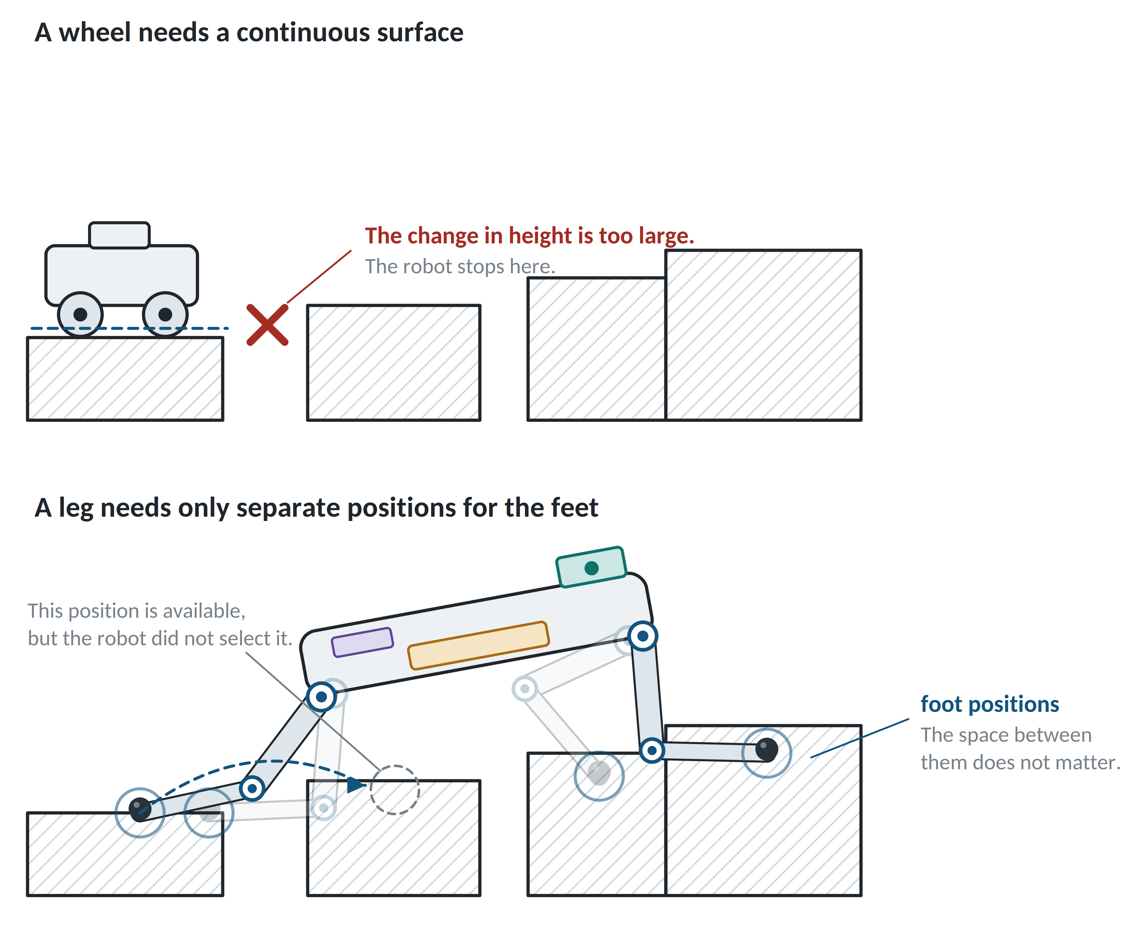
Stairs, curbs, pipe racks, stone beds and open steel gratings present similar barriers to a wheeled robot because navigation software cannot resolve the lack of a suitable surface. These features are common in buildings and infrastructure designed around human movement. People can use stairs, thresholds, curbs and ladders, so a site that is accessible to a person may still be difficult for wheels. Legged robots are better suited to this terrain, although the choice of four legs rather than two also involves stability.
Why four legs, and not two
One reason for using four legs is the support available when the robot slows down or stops. A robot stays upright while its center of gravity lies above the area between its feet, known as the support area. A larger area gives it more room to tolerate a push or an inaccurate step.
Lifting one of four feet leaves a triangle of support, allowing the robot to hold its position and wait. Lifting one of two leaves a single footprint with almost no support area in the forward direction.
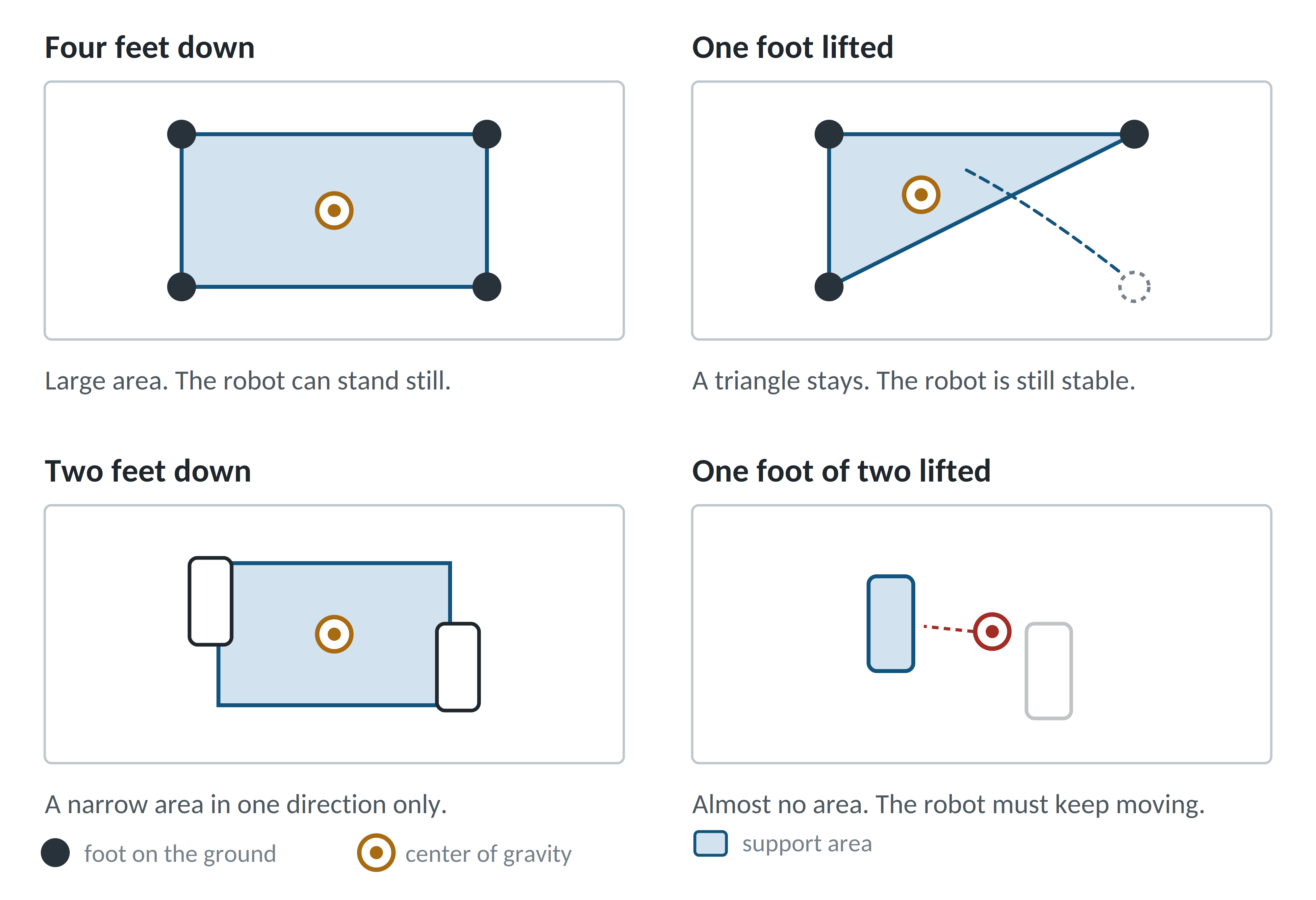
A two-legged robot has to keep correcting its forward fall, and an interruption to that control can cause it to fall over. A four-legged robot with three feet on the ground can remain standing indefinitely.
Horses illustrate the same principle: they can lock their legs and rest standing on four supports [4]. A person standing still continues to balance on two legs, whether awake or not.
When terrain becomes difficult or camera observations become uncertain, a quadruped can slow down and keep more feet on the ground, eventually stopping if necessary. A two-legged robot cannot increase its number of supporting contacts in the same way.
Six legs would enlarge the support area further, but that extra margin is rarely needed. It comes with fifty percent more motors, mass, cost and opportunities for failure. Four is the smallest number that leaves three supporting feet when one is lifted.
How the robot pushes itself forward
Each foot cycles between two conditions:
-
Stance. The foot carries load and pushes against the ground.
-
Swing. The foot travels through the air to its next position.
The fraction of the cycle spent in stance is the duty factor [5]. It determines how many feet stay down at a given moment, affecting both stability and speed.
Four-legged animals use a small set of movement patterns, changing between them as speed increases [5]. Robots adopt the same patterns because they face the same physics. Borrowing an established gait also produces faster, more natural-looking motion than designing one from scratch.
Most quadruped motion uses one of four gaits.
-
Walk. Duty factor 0.75. Only one foot lifts at a time, leaving three on the ground. It is slow, and the only gait here that stays stable at every instant.
-
Trot. Duty factor 0.50. Diagonal pairs move together, balancing the load across the body. This is the usual choice for steady travel.
-
Pace. Duty factor 0.50. Both legs on one side move together. The gait is efficient on smooth ground, though it rolls the body from side to side. Camels and some horses use it.
-
Gallop. Duty factor below 0.50. The legs land in sequence, with a period of flight during which all feet leave the ground. It is the fastest and least forgiving gait.
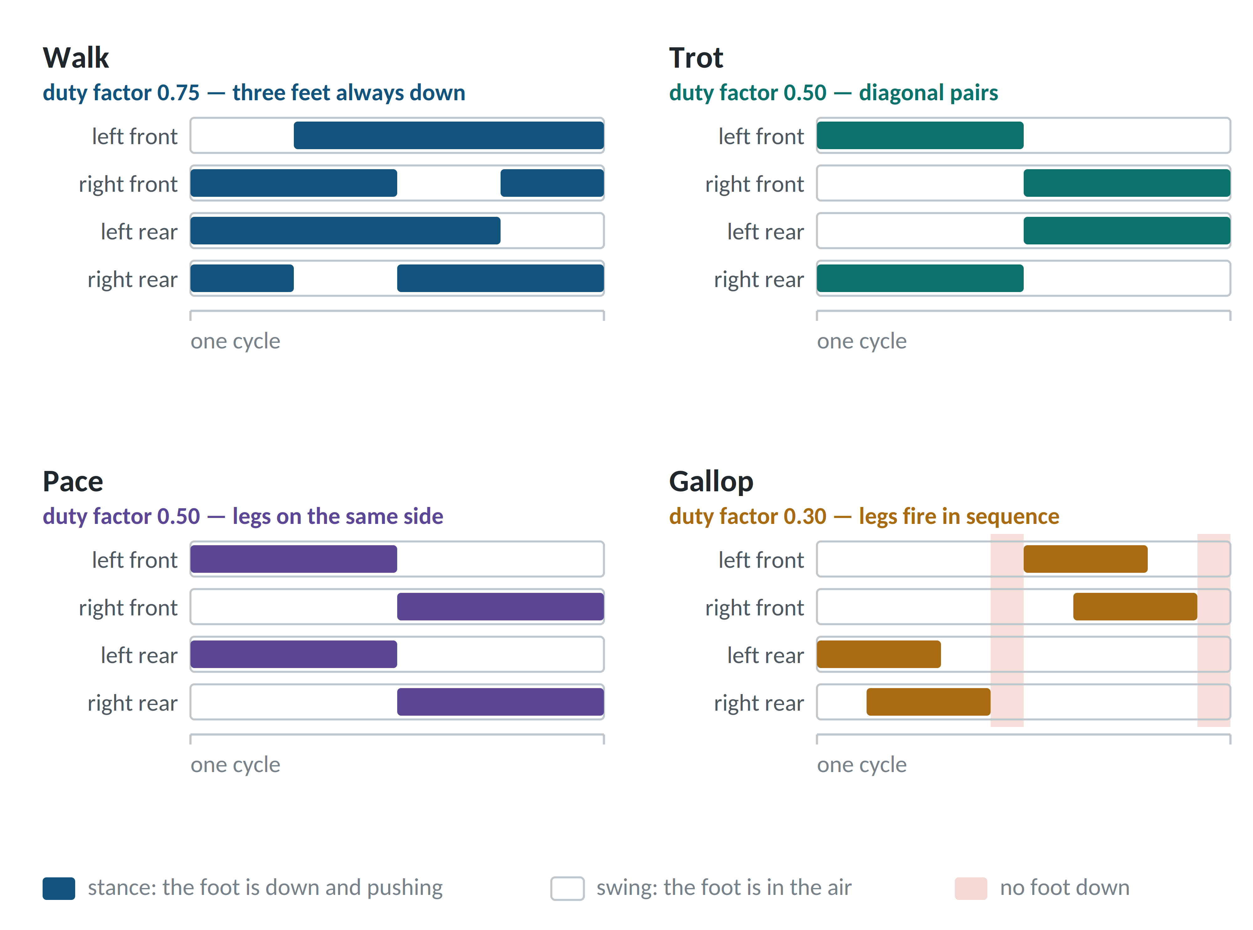
The gallop panel has two intervals per cycle with no bar, corresponding to periods when the machine is airborne. During these intervals, it has no contact to support its weight or provide a position measurement, which affects the sensing system discussed below.
During stance, the motors rotate the leg so its foot presses down and backward. The ground returns an equal force directed up and forward: the upward component supports the robot’s mass, while the forward component propels it. Adjusting the push angle changes how the force is divided between support and propulsion.
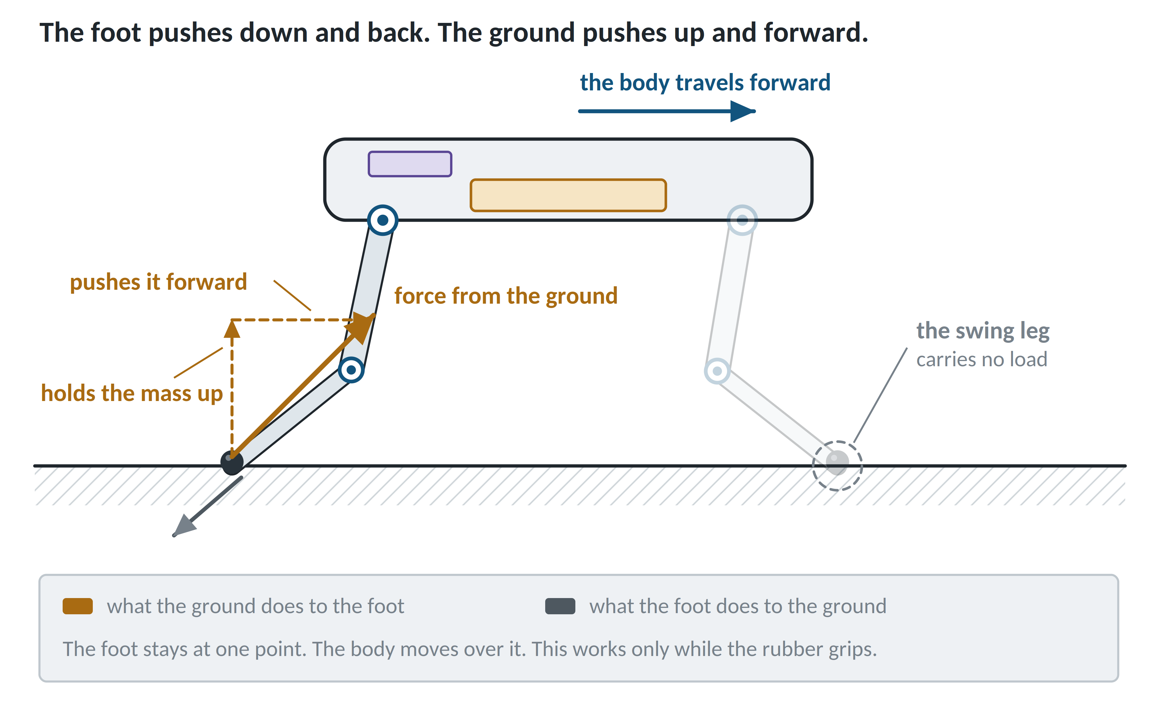
Throughout this movement, the foot stays fixed on the ground. The body passes over it while the leg sweeps backward underneath. At the limit of its travel, the foot lifts, swings forward, and lands at the next position.
The same mechanism applies when a person walks on a hard floor. On wet tile, the foot may slide instead of moving the body forward because the surface cannot provide enough sideways force. The robot is subject to this friction limit at every step, with the ratios discussed earlier of about 0.8 on dry concrete and about 0.2 on wet steel.
Gait selection happens as the robot moves, based on the required speed, terrain conditions, and confidence in its observations.
Inside one leg
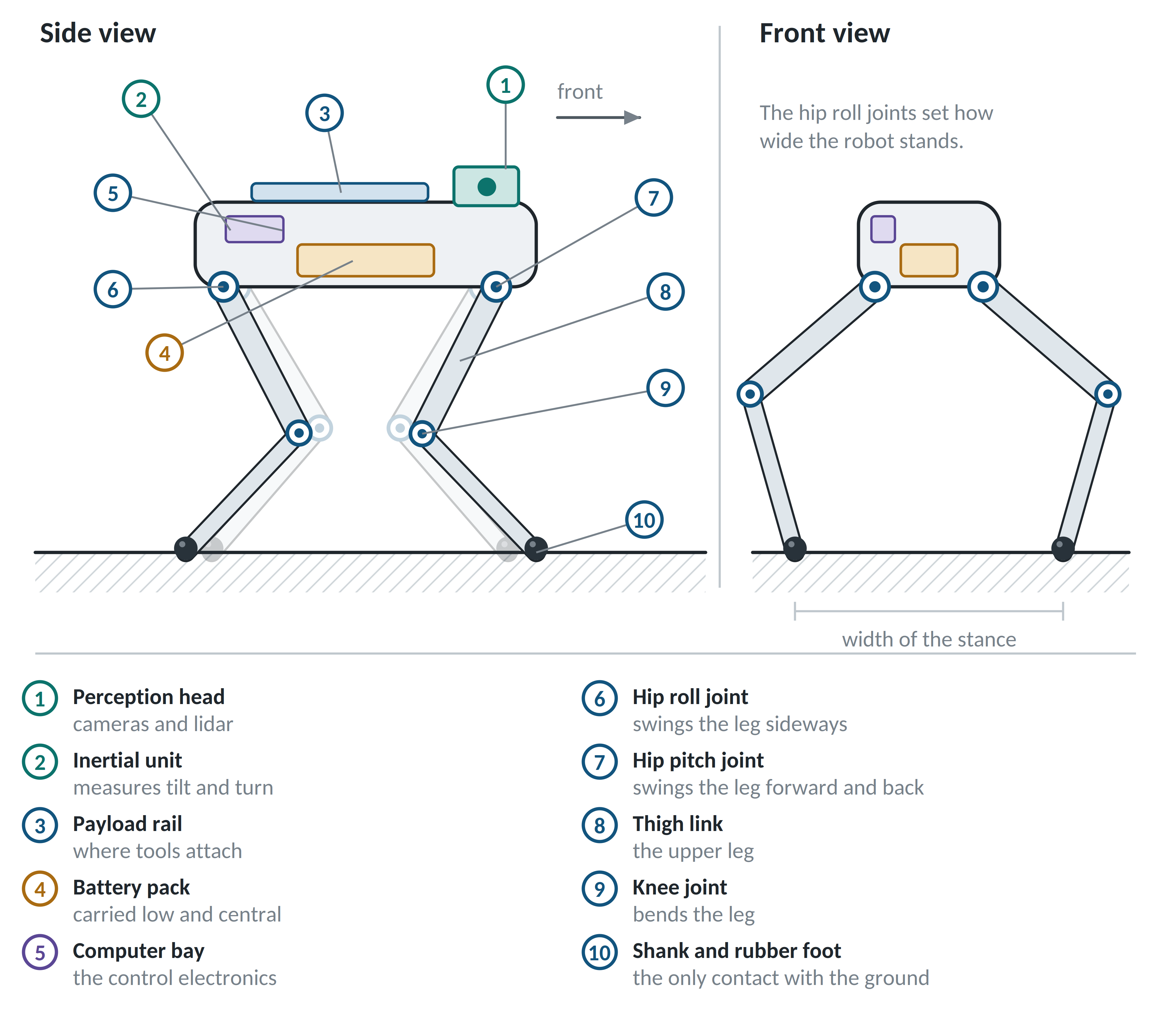
The three motors in each leg divide the work as follows.
-
The hip roll motor moves the leg sideways, sets the stance width, and takes the load from a sideways push.
-
The hip pitch motor swings the leg forward and backward, doing most of the work during walking.
-
The knee motor bends the leg to set its downward reach and lift the foot over obstacles.
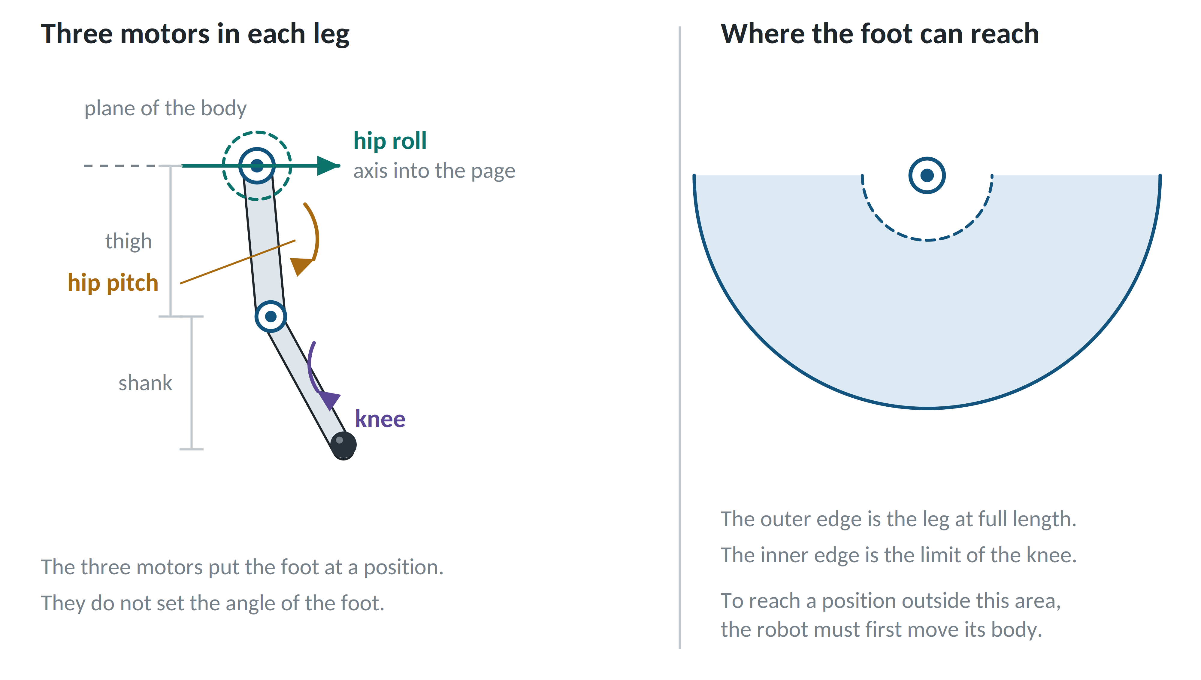
These three motors control foot position but not its angle. Most quadrupeds have no ankle and use a rubber ball as the foot. This choice affects how the robot balances: without an ankle, it cannot apply a twisting action against the ground or correct its balance through a single foot.
The robot instead relies entirely on foot placement and contact forces. Four feet provide enough control through these two means, whereas a two-legged robot needs a flat foot, an ankle, and a large motor at the bottom of its leg.
The other major design rule is to concentrate mass in the body. Light legs swing quickly with less disturbance to the body and suffer less damage on hard landings.
Light legs also simplify the computation. The robot can be approximated as a solid block supported by four thin legs, allowing the model to be evaluated between steps. With heavy legs, this approximation no longer holds and the software has to account for the motion of every part of each leg. Early decisions about mass distribution therefore affect how much computation the controller will need later in development.
In the hardware, each joint combines its motor, gearbox, electronics and sensors in a single housing.
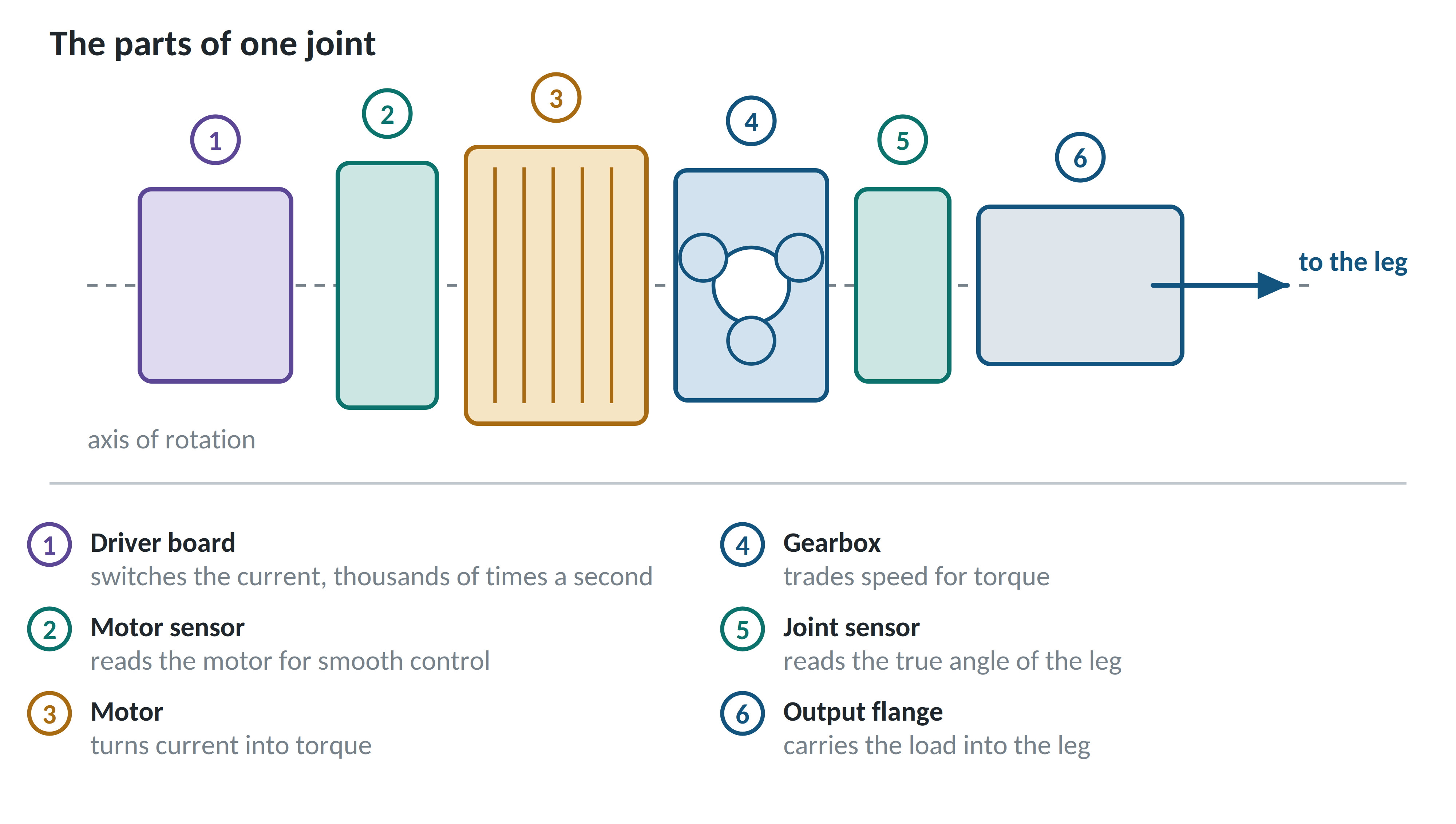
One sensor measures the motor for smooth control, while the other measures the output to give the true leg angle as soon as power is switched on. Without the output measurement, the robot would have to move each leg to establish its position.
Most electric quadrupeds use low gear ratios, from 6:1 to 10:1. Higher ratios provide strength but isolate the motor from forces at the ground. A low ratio preserves that sensitivity and lets software set the leg’s stiffness without a physical spring. The controller can change the stiffness between touchdown and push-off.
What the robot senses
When you carry a large box down a corridor, you keep walking even though your feet are hidden. Each step tells you about the floor, allowing you to notice a threshold before tripping over it.
This sense of your own body is called proprioception, a term also used in robotics. It covers where each part is, the load it carries, and contact with its surroundings. A quadruped obtains it from joint sensors, motor currents, foot contact sensors, and an inertial unit that serves a similar purpose to the balance organ in the inner ear.
These sensors provide fast, continuous feedback regardless of weather. A quadruped with suitable control can cross rough ground with its cameras switched off by detecting each surface through touchdown, much as a person can feel their way across a dark room.
Depth cameras, lidar, and inspection equipment form the second sensor group. They are slower and can fail in fog, dust, rain or bright sunlight, but they let the robot see terrain before reaching it. With that information it can choose footholds in advance; without it, the surface becomes known only at touchdown.
Vision helps the robot plan its movement, but the balance controller needs to continue operating when the view is obscured. Otherwise, a loss of camera visibility would also mean a loss of balance.
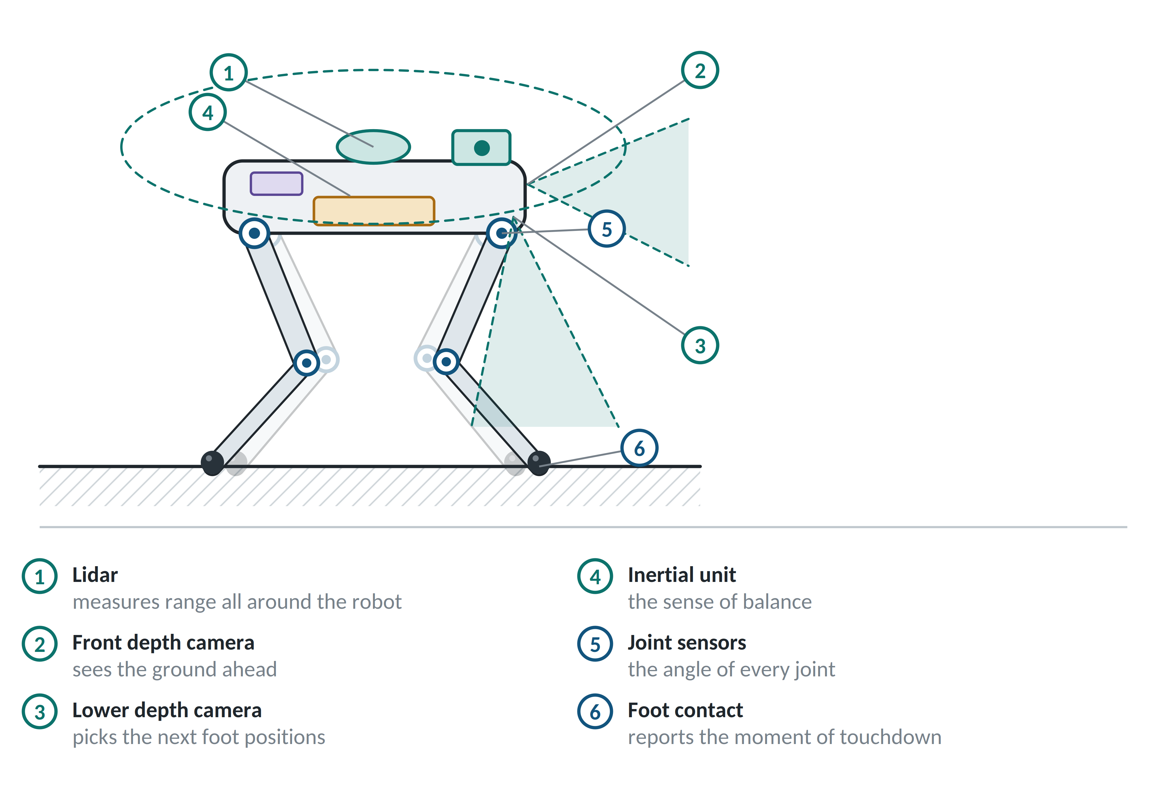
These sensors do not directly measure body position, so it has to be estimated. If a grounded foot stays fixed, the leg geometry reveals how far the body has moved over it. This information corrects the inertial unit’s gradual drift, making reliable contact data important to the position estimate.
This adds another difficulty to fast movement beyond the larger forces. During a fast trot, all four feet briefly leave the ground. Until the next touchdown, there is no contact measurement to correct drift and the robot’s position estimate is less certain.
Power and computers
The battery pack feeds a management board that protects the cells and divides the supply into separate motor and electronics lines.
The power system has to accommodate peaks as well as sustained operation. A steady walk takes a few hundred watts; a hard landing can demand several kilowatts for a few hundredths of a second. Over longer periods, heat limits performance before strength does. Motor windings warm up, with stairs usually exposing the thermal limit first.
Computation is divided across three levels according to the response time each task needs. This is similar to the nervous system, where withdrawing a hand from a hot pan begins with a signal through the spinal cord before conscious processing in the brain.
-
A small controller inside each joint maintains the commanded torque tens of thousands of times a second, serving as the reflex.
-
A real-time computer updates balance several hundred times a second, corresponding to the spinal cord and brain stem.
-
A vision computer builds maps and plans routes tens of times a second. It handles the slower, deliberative work.
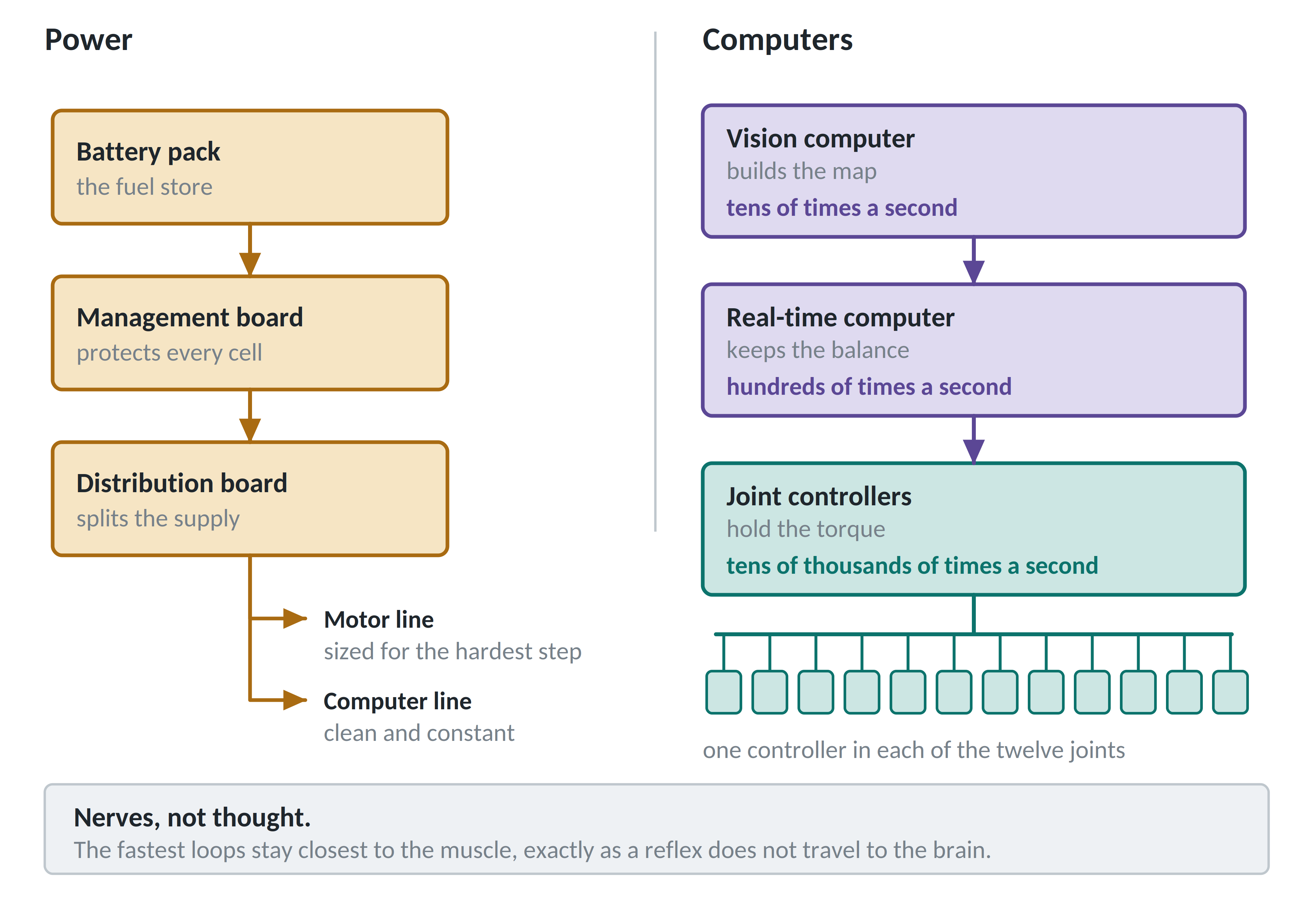
The computers communicate over a data bus with predictable delivery times. A constant delay of two milliseconds can be compensated for, whereas a delay that varies between half a millisecond and three has no fixed correction. Consistent timing is therefore more important here than raw communication speed.
How the robot decides
The hardware allows the robot to apply an accurate force to the ground. Calculating the required force, about a thousand times a second, involves indirect control of the body, changes in mechanics at touchdown, unmeasured friction, and uncertainty in body position. These problems are handled across control layers with different responsibilities and update rates, rather than by a single method.
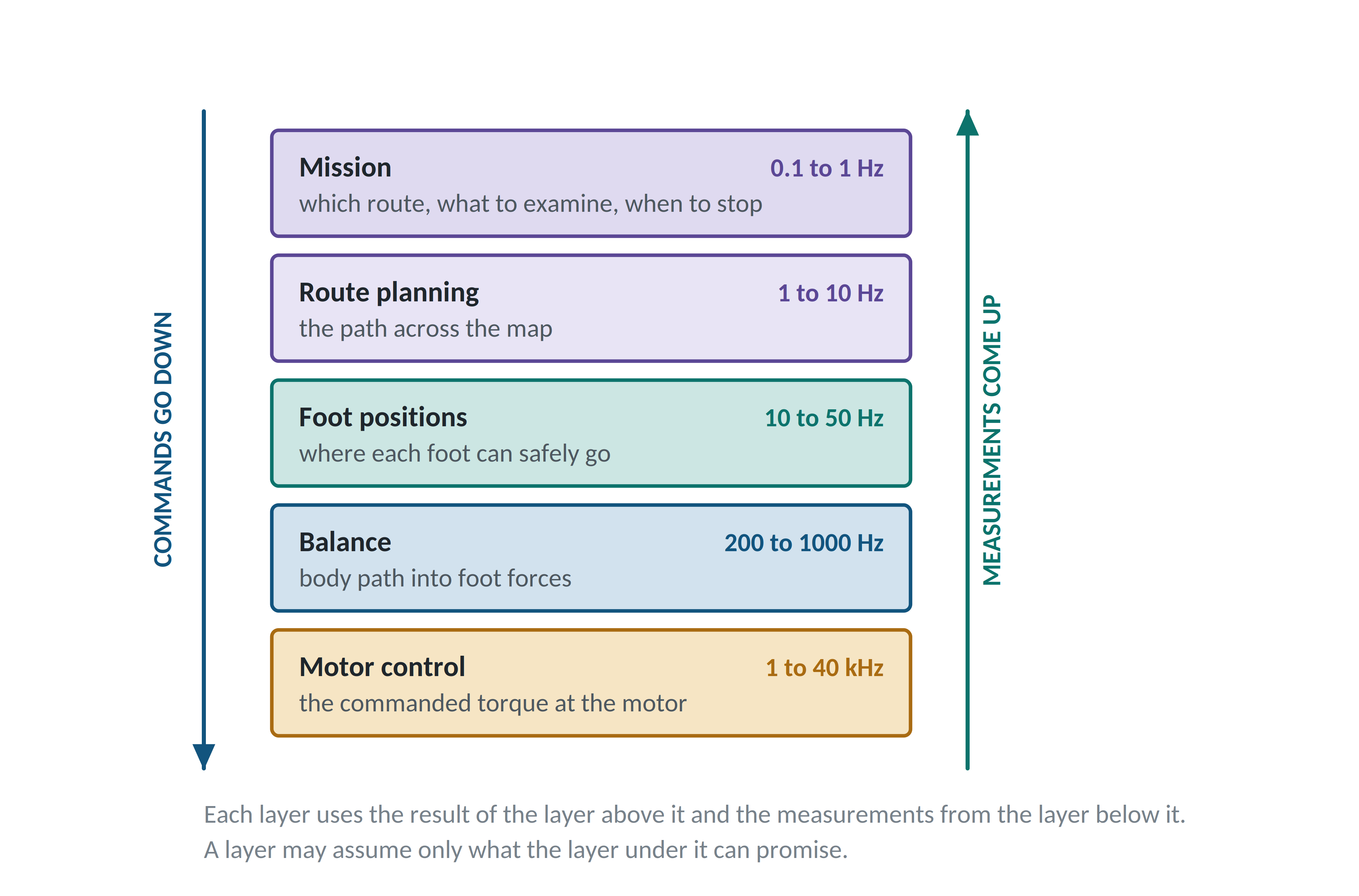
The task is translated into a route, then foot positions, then a body path and foot forces, and finally currents in twelve motors. Each stage supplies what the next one needs.
Three families of methods occupy these layers. Their usefulness depends on how well the robot model can be trusted for the job.
-
Classical control suits fast loops with accurate models. Following a motor torque command is a well-understood problem backed by a century of theory, so almost every quadruped uses it in its lowest layer.
-
Model-based control is useful when constraints determine the action. It accounts for slip, loaded feet and motor limits over the next fraction of a second, then plans within those limits.
-
Learned control is useful where the model is least accurate, including soft ground, loose stones, slipping contacts, and surfaces that resist a useful equation.
These methods address different questions, and real robots use all three within the same machine.
Above them sits the layer responsible for the job: choosing a route, deciding what to inspect, and knowing when to stop and ask a person. It needs feedback from every level. A hot motor, an uncertain map, or a lost radio link changes what is reasonable to attempt next. Without motor-temperature feedback, this layer can keep issuing orders until the motor fails.
The layers also respond at different times. A push triggers the joint controller within about a millisecond and the footstep planner a few hundred milliseconds later, with four responses in all. The quadruped control architecture article in this series describes the timing and responsibilities of each layer in more detail.
How to make one walk
Developing reliable walking behavior usually takes longer than building the hardware. The process begins with the intended job and terrain, including obstacle height, gap width, slope, payload, operating time and sealing requirements. These determine the leg dimensions, motor requirements, and the rest of the design, so changing them late in development can require substantial work to be repeated.
Once the requirements are set, the machine can be tested at progressively more demanding levels, as shown below.
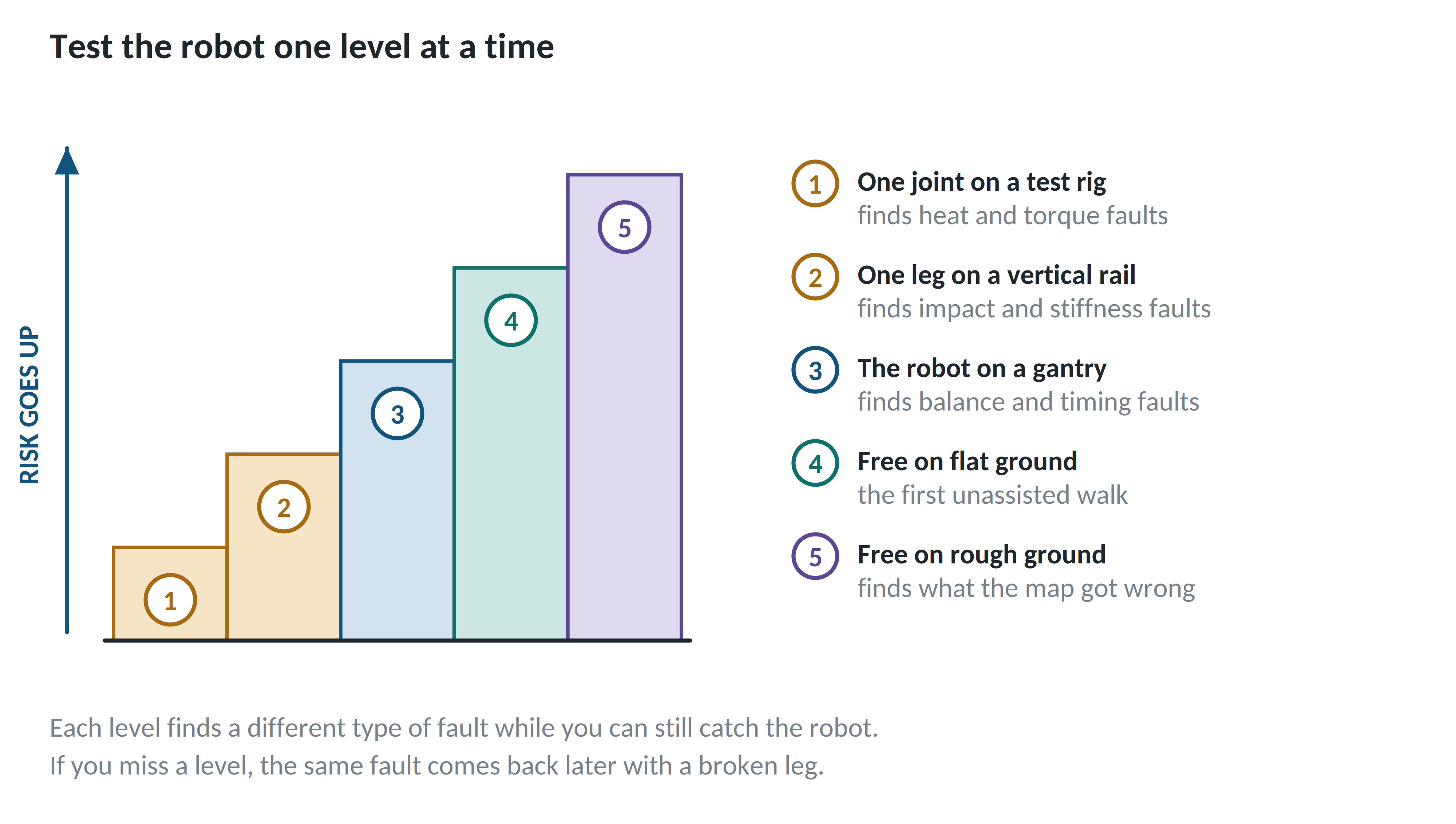
Further development involves measuring the differences between simulation and the physical robot. Measurements of the actual motors, delays and contacts can then be used to refine the design and its models. Understanding these differences is one of the most useful outcomes of the development process.
References
[1] Boston Dynamics. Spot specifications. 32.5 kg, 14 kg payload, 605 Wh, approximately 90 minutes of operation, 1.6 m/s, IP54, 300 mm maximum step.
[2] ANYbotics. ANYmal D specifications. Approximately 50 kg, 10 kg payload, 932 Wh, 90 to 120 minutes of operation, 1.3 m/s, IP67.
[3] Bjelonic, M. et al. Keep Rollin’ — Whole-Body Motion Control and Planning for Wheeled Quadrupedal Robots. arXiv:1809.03557. Mechanical cost of transport when driving against trotting.
[4] Hildebrand, M. Symmetrical Gaits of Horses. Science, 1965. Support patterns and standing rest in quadrupeds.
[5] Alexander, R. McN. The Gaits of Bipedal and Quadrupedal Animals. International Journal of Robotics Research, 1984. Duty factor, gait selection, and the change of gait with speed.
[6] Typical dry and contaminated friction values for rubber against concrete and steel. Values vary with compound, load and surface condition, and a controller must not depend on a fixed number.
Manufacturer figures change between product generations. Check the current data sheet before you rely on any number quoted here.